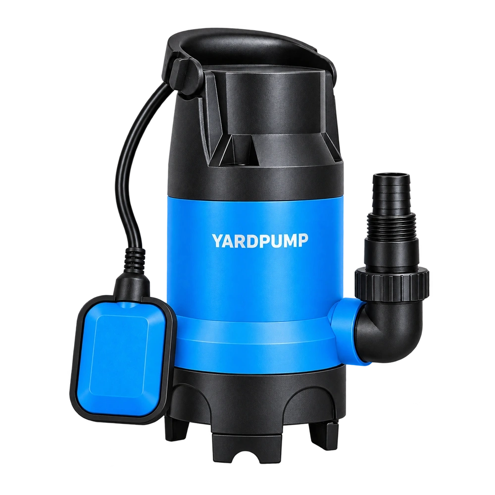
A printed impeller fits inside a pump and moves water. Is the model ready for injection-moulded production? The trial can support development, but one water test does not release the moulded version. Identify what the prototype demonstrates: shape, assembly, hydraulic tendencies or material performance. Printing and moulding have different process boundaries, so conclusions must remain within what the particular sample actually verified.
A prototype has a declared job
A visual model supports spatial and design discussions. An assembly model checks interfaces and installation sequence. A functional prototype helps investigate operation. These models may use different materials, accuracy and post-processing. A part suitable for checking interference is not automatically suitable for design speed, and a controlled short trial does not establish endurance or sealing reliability.
Define the purpose before selecting the manufacturing method and test conditions. “Printed sample approved” is inadequate without that purpose. For rotating components, competent engineers must establish whether operation is permitted, the protective arrangement and stopping criteria. Development work is not an invitation for users to print an impeller and install it in everyday service.
Record layers, surfaces and internal condition
Additive processes differ in bonding, porosity, dimensions, surface and directional behaviour. A limitation of one printing method should not be applied to every method. Equally, a nylon description does not establish equivalence with an injection-moulded glass-filled nylon grade. Record material identity, build direction and post-processing with the sample.
Surface condition and actual clearance may affect a short hydraulic test. Internal structure and directionality can affect load capacity. If a bore or vane edge is machined or sanded to fit, record the location and resulting dimensions. Otherwise the test result may later be assigned incorrectly to the unmodified digital model.
| Prototype purpose | Useful evidence | Not automatically established |
|---|---|---|
| Shape review | Space and design communication | Safe speed or load capacity |
| Assembly review | Interfaces and operation sequence | Long-term torque retention |
| Controlled functional trial | Behaviour of that particular sample | Moulded production consistency |
| Moulded validation sample | Behaviour of the specified process | Behaviour after untested changes |
Moulding introduces new variables
Injection-moulding development must address shrinkage, release, gates, flow-front junctions, fibre orientation, thickness transitions and cavity variation. A problem absent from the printed model may emerge in the tool. Conversely, a loss caused by a rough printed surface may not remain in a moulded part. Results can inform development without being merged into one unidentified performance curve.
As an illustrative division of work, a printed sample might establish that the proposed geometry fits an existing chamber, while moulded samples support final hydraulic and endurance validation. This is not a mandatory universal programme. The essential requirement is that each decision is linked to an appropriate sample and evidence rather than extending exploratory findings beyond their capability.
Freeze the release definition before tooling
Identify the three-dimensional model, dimensioned drawing, candidate material, critical interfaces and operating objectives, with unresolved questions listed explicitly. A quotation should explain tooling, trials, sample quantities and support for validation. A successful print does not remove the possibility of mould adjustments. Critical dimensions also need datums and measurement methods, not merely a surface model.
Retain the reason and revision whenever vane thickness, radii or the bore changes. Revalidate affected hydraulic or structural behaviour. Converting a prototype model into a moulded design is itself a controlled design step. Purchasing, tooling and testing must not work from separate unlinked revisions.
Release the manufacturing configuration
Final acceptance should use samples made with the intended production material, tool and process. Complete the agreed dimensional, assembly, load, performance, thermal and relevant reliability checks. Where appropriate, examine consistency across cavities or batches. Prototype success can shorten the learning cycle without becoming a claim about production life or safety.
A useful development report explains both what the printed sample taught and what remains open. That allows an OEM buyer to fund the next step for a concrete reason, rather than assuming every later test repeats work already completed.
Questions about printed impellers
Can a printed impeller help predict performance?
A suitable, safely controlled trial can provide clues. State differences in material, surface, clearance and production configuration.
Why test moulded samples if the model is unchanged?
The process changes physical dimensions, internal condition and surfaces. The same digital geometry does not establish identical component behaviour.
Does a failed print prove the design is unsuitable?
Not necessarily. Separate design weaknesses from prototype-process limitations before changing the geometry, process or test method.