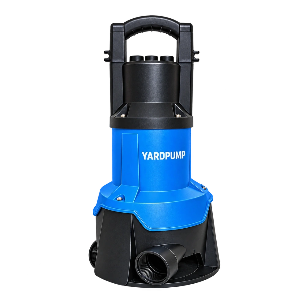
Imagine an incoming lot of plastic submersible pump outlets passes the thread gauges. An assembler then notices a thin ridge inside the bore. Some material sits against the wall; some looks as if it could bend in the water. Can the lot be released on the thread result? Thread fit and passage condition are separate checks. Locate the edge and establish whether it can restrict flow, affect the sealing interface or detach into downstream equipment.
A thread gauge has a defined job
An approved thread gauge checks the relevant thread requirement. A part that accepts the gauge may still have a ridge inside a cross hole, at the end of the bore or inside the adaptor. Mould flash, machining fragments and material shaved during assembly can appear in different places. A thin flap can sit out of the way in a dry check and move under flow. Loose material can end up in a nozzle, valve or filter. Do not call every visible mould line a defect; identify the location and the released requirements for the edge and passage.
Treat the thread, sealing surface and effective flow passage as separate areas. Record the gauge and conditions for the thread. Check the sealing surface for projections that could affect the joint. Inspect the bore for prohibited ridges and debris. Where direct viewing is difficult, use suitable lighting and inspection equipment. Use a released tool for a minimum opening check rather than scraping the plastic with a sharp object. A boundary sample can help when inspectors must distinguish a harmless line from a loose flap.
Check the effect before deciding on disposition
For illustration, a circular 22 millimetre opening has an area near 380 square millimetres. If a uniform ridge reduces its effective diameter to 20 millimetres at the narrowest section, that section has about 314 square millimetres, roughly 17 percent less area. This is not a measured flow loss. Local shape, length, the pump curve and downstream resistance affect flow, and a one-sided ridge cannot be represented as a smaller round bore. The example shows why thread size is not a measurement of the water passage.
Agree on defect location, inspection method and cleanliness expectations before the order ships. When debris appears, preserve the particle and its location. Determine whether it came from the moulding, an accessory or assembly. Trace the possible production scope by cavity, shift, machining operation or assembly interval before removing the evidence. If rework is permitted, define the tool, cleaning process and subsequent checks for size, debris, fit and required performance. Do not ask a user to enlarge the passage or shave sealing features.
Release both the joint and the passage
Confirm that rework preserved the original fit and sealing geometry and did not create new debris or restrictions. A tiny sprinkler or drip outlet can be sensitive to loose particles even when total flow is initially acceptable. A general example cannot set a universal minimum bore or burr allowance for a different material and application. Put bore condition on the acceptance record as its own decision, instead of trying to infer it from a passing gauge.
For a recurring finding, mark the mould split, tooling approach and assembly contact on the same inspection image. Distinguish cavities or stations if they leave different marks; averaging them in one group can hide the source.
Frequently asked questions
Does a visible mould line require rejection?
Not by itself. Check its position, size, stability and released requirements. A harmless surface line is different from an obstruction or loose particle.
Can a rinse with no visible debris release the lot?
Follow the approved rework and retest plan. One clean rinse cannot establish the source of debris or the status of other parts.
Can a larger discharge hose compensate for the ridge?
A larger hose may change system losses, but it cannot remove the risks from a loose fragment or affected seal. Resolve the component condition first.