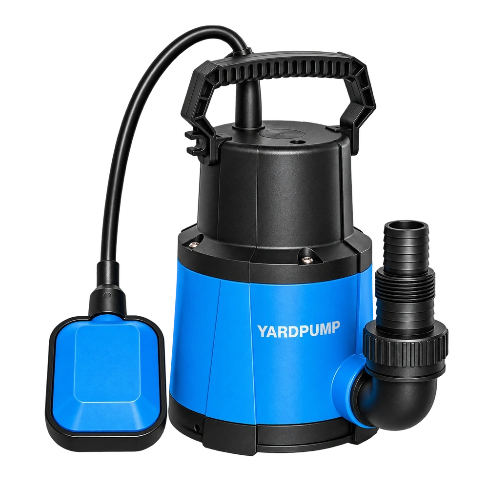
Two sump installations can use the same pump and check valve and be very different to service. A valve fitted high on the riser can leave more water below it to run back into the pit. The union location determines which section opens during pump removal. Start with the manufacturer’s required arrangement, then check access and the volume on each side.
Draw the joints and shade the water that can return
Valve position changes the water column retained above the pump and which section drains during removal. It can also change joint loading, air pocket behaviour, access to the union and the volume that flows back into the pit.
Mark the pump, union, valve, support points and drain destination. Include any specified air-release provision. When the valve closes, the line on the discharge side can remain full. If water on the pump side can drain through the pump, that part will add to the pit after each stop. Moving the valve changes where these volumes begin and end.
For example, lifting the valve by 300 mm on a vertical section with a 40 mm clear bore adds about 0.38 L of capacity to the pipe below it, assuming that added section is straight and full. That may have little effect in a large pit. In a very small switching volume, add it to the rest of the expected return before judging the cycle.
Place the union for the real removal path
If the manufacturer allows a union on the pump side of the valve, the valve can remain attached to a supported discharge section during service. Plan a controlled drain and depressurization for any section opened. If the joint opens above the valve, assess the water on that side of the system and the way it can be drained. Valve leakage or another part of the plumbing can change which section is full, so confirm the actual state before removing connections.
Ensure the fixed riser remains supported as the pump is removed. The pipe and any union should line up without forcing the pump toward one side. Allow room for the wrench, basin cover, cable and approved lifting arrangement. Where instructions place the valve at a specified height or orientation, follow that detail and solve access around it.
Verify the assembled installation
Draw the final vertical route with pump outlet, vent feature if specified, union, valve, supports and cover. Wet-cycle it, isolate power and pressure, then rehearse removal without standing beneath or releasing an uncontrolled water column.
Release the exact valve location, orientation, support and service sequence on the installation drawing, and verify that the pump can be removed without unsafe trapped water or pipe load.
Record the final positions and the service procedure, including where the water goes when the line is drained. Observe wet cycling and water returning at stop from an appropriate location. Then review venting, valve losses and any applicable installation requirements against the installed design.
Frequently asked questions
Should the check valve always be directly on the pump outlet?
Use the model and valve instructions. Choose a permitted position with suitable access, support and expected drainback.
Can I loosen the union when the pump stops?
Isolate the pump, support the pipe and follow the approved drain and pressure-relief procedure first. A stopped pump can still have water retained in the discharge system.
Why can a higher valve make cycles shorter?
More water can remain below the valve and return to the pit. Compare the potential return volume with the effective on/off storage band.