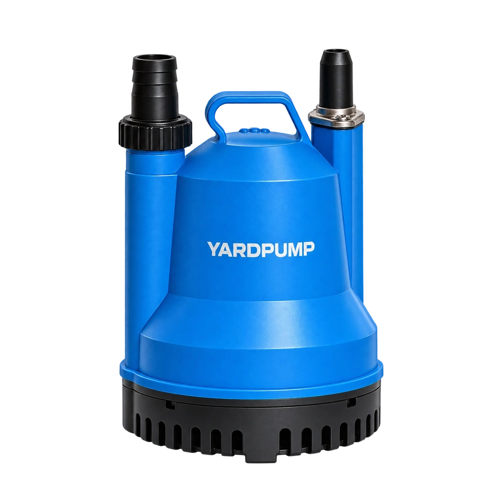
A ground-level rainwater tank feeds an elevated day tank. The day tank needs water in the afternoon, but the source sometimes runs low overnight. A float at the receiving tank can stop an overflow; it cannot tell whether the source still covers the pump inlet. Give the two tanks separate conditions. The destination asks for water and ends the fill. The source grants permission to run and removes it when the intake cannot remain safely supplied.
Write a behaviour table before choosing the controls
When the receiving tank falls to its refill mark, it should request a fill. At its upper mark, it should cancel that request. When the source falls to its protective level, the pump should stop or stay off, even if the receiving tank remains low. Recovery of the source level restores permission; it should not start the pump if the destination is already satisfied. If the source refills slowly, a distinct recovery level can help avoid restarting on every small incoming trickle.
| Observed state | Expected response |
|---|---|
| Destination requests a fill and source permits withdrawal | Start under the approved control logic |
| Destination reaches its high stop level | Stop and check how much more water arrives |
| Source reaches its protective low level | Stop or inhibit the pump, with an identifiable low-source condition |
| Power is restored | Verify the specified restart behaviour under supervision |
A control scheme also needs a defined response to a broken wire, obstructed float or unstable reading. Do not guess what a disconnected input means. Record which state is safe for the installation and use controls and motor switching arrangements approved for the exact hardware. An electrical installer should handle the connections; do not bridge a protective input to get an inconvenient pump started.
Calculate the lift at the useful extremes
A pump may fill the day tank easily with a full source, then slow down when the source is low. Measure the elevations and account for hose, filter and fitting losses. If a receiving outlet discharges freely above the water, use that outlet elevation. If it remains submerged, the receiving liquid surface is part of the hydraulic boundary. A high point can trap air on startup, and a filled line can release water after shutdown or permit reverse flow. A separate safe overflow route is a design feature, not a substitute for functioning controls.
Consider an illustrative day tank with 30 litres between the high stop mark and the overflow. Delivery is 60 litres per minute and takes eight seconds to stop after the signal, contributing about eight litres. If another 12 litres drains from the line toward the tank, the initial 30 litre margin falls to 10 litres. That estimate omits level error, surge and another inlet. Measure what really happens on shutdown and provide a suitable overflow path instead of moving the float closer to the top.
Verify the transitions, not just the wiring
Watch a normal fill, high-level stop, low-source interruption and supervised power restoration. Keep liquid level, control indication and motor state on the same timeline. Look for a level switch disturbed by an incoming jet, a float held by the tank wall, or a pump that runs after its command is off. Document both test levels and actual delivered flow; a wiring diagram alone will not show what happens with waves or a hose that drains backward. When the hose, pump or sensor position changes, recheck the protection levels and the post-stop volume.
Frequently asked questions
Can any two floats simply be wired in series?
No. Check the permitted contact logic, electrical load, failure state and controller instructions. A correct behaviour table is not a wiring plan.
Could the inlet draw air before the source float stops the pump?
Yes. The float reports level where it is mounted. An inlet elsewhere may be higher or affected by a vortex. Verify minimum submergence and set the protective level for the installed arrangement.
Why does the destination still fill when the pump is off?
A trapped pipe volume can drain into it, or the layout can sustain a siphon. Distinguish a finite run-on from continuing flow and provide the appropriate approved isolation, backflow or overflow provisions.