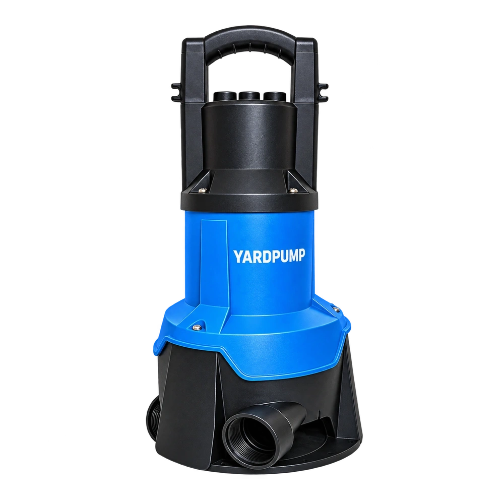
Consider this illustrative welding-acceptance problem. “The ultrasonic welder reports that the energy target was met, yet the plastic pump leaks. Are the machine records useless?” The records are useful, but meeting an energy setting establishes only that a process variable satisfied the machine’s criterion. It does not independently prove a continuous, adequate or durable seal. Joint design, component consistency, process inputs and actual joint results must be validated together.
A total energy value does not show where energy acted
Ultrasonic welding combines vibration and force to generate local heating and fusion at the interface. Geometry, energy-directing features, fixture support and material condition influence how energy reaches that interface. The same total energy can accompany different contact patterns, melting distribution and collapse behaviour.
If the fixture is unstable, the parts are distorted or the interface is contaminated, energy may be consumed outside the intended sealing path. The machine can reach its target while part of that path remains inadequately joined. Adding more energy without investigation may instead produce excessive flash, distortion or damage.
Collapse information also needs context
Collapse or displacement data can help explain geometrical change during welding. Interpret them against starting dimensions, fixture compliance and the machine’s measurement method. Equal recorded displacement can arise from different initial conditions; it is not an independent measurement of uniform fusion around a joint.
| Process or design information | What it can reveal | What it cannot prove alone |
|---|---|---|
| Energy, time and power trace | Process changes or abnormal consumption | A sealed complete joint |
| Collapse or displacement | Changes during fusion and compression | Equal bonding everywhere |
| Force, amplitude and hold phase | Input and fixation conditions | Long-term temperature and pressure durability |
| Joint examination and leak testing | Actual joint outcomes | Suitability for every application |
Use a validated combination of process limits rather than a single “energy accepted” signal as the complete release criterion.
Joint design precedes parameter adjustment
The sealing path needs appropriate geometry and continuity. Location features should bring the components into the intended contact. Energy directors, wall transitions, radii and accommodation for displaced material can influence fusion and subsequent loading. Machine settings cannot compensate for every unsuitable joint design.
Materials also need compatibility and control. Resin grade, reinforcement, moisture condition, reprocessed-material content and surface contamination may affect weldability. Two parts are not necessarily compatible because both are plastic. Likewise, settings established for one pump geometry cannot simply transfer to another.
The fixture and horn belong to the validated arrangement. A change to either can alter local loading and energy transmission even if the programmed energy value remains unchanged.
Establish a process window using actual results
During development, evaluate a defined range of settings with controlled components and tooling. Examine the resulting joints and leakage performance while considering normal tolerances and process variation. Test medium, pressure, duration and detection sensitivity should come from the approved procedure rather than an operator’s improvised pressure increase.
If the joint will experience temperature cycling, extended immersion or external loading, include appropriate durability validation. A short leak test represents one point in time. Destructive examination can help understand joint formation, but its method, frequency and acceptance criteria should be specified in the design and quality plan.
Record the relationship between accepted process traces and successful joint outcomes. This provides a reasoned basis for production monitoring rather than assuming that any repeatable trace must represent a good weld.
Connect production records to returned parts
Link program version, horn and fixture identification, material batch, relevant traces and leak-test results. Reassess changes such as a replacement horn, repaired fixture, resin substitution or component revision according to risk. Significant process drift deserves investigation even before leakage is observed.
For a complaint, isolate the pump and establish whether the leak actually originates at the welded joint. Preserve the failure location and service conditions, then compare them with the original batch records. A machine acceptance record does not rule out a weld problem; water near a weld does not rule out another ingress path.
This discussion applies to plastic joints that use ultrasonic welding. It does not imply that every YARDPUMP model uses that construction. Confirm the actual product arrangement before applying the method.
Frequently asked questions
Is increasing energy the simplest improvement?
Not necessarily. It can produce excessive collapse, flash or damage. Adjust only within a validated development process and examine the resulting joints.
If every weld trace looks similar, is leak testing still needed?
Follow the approved quality plan. Similar traces demonstrate part of process repeatability, not independent proof that every sealing path is complete.
Can a leaking weld be patched with adhesive and shipped?
Only under an approved repair procedure with appropriate revalidation. Compatibility, durability and traceability must be established; an improvised patch should not hide process instability.