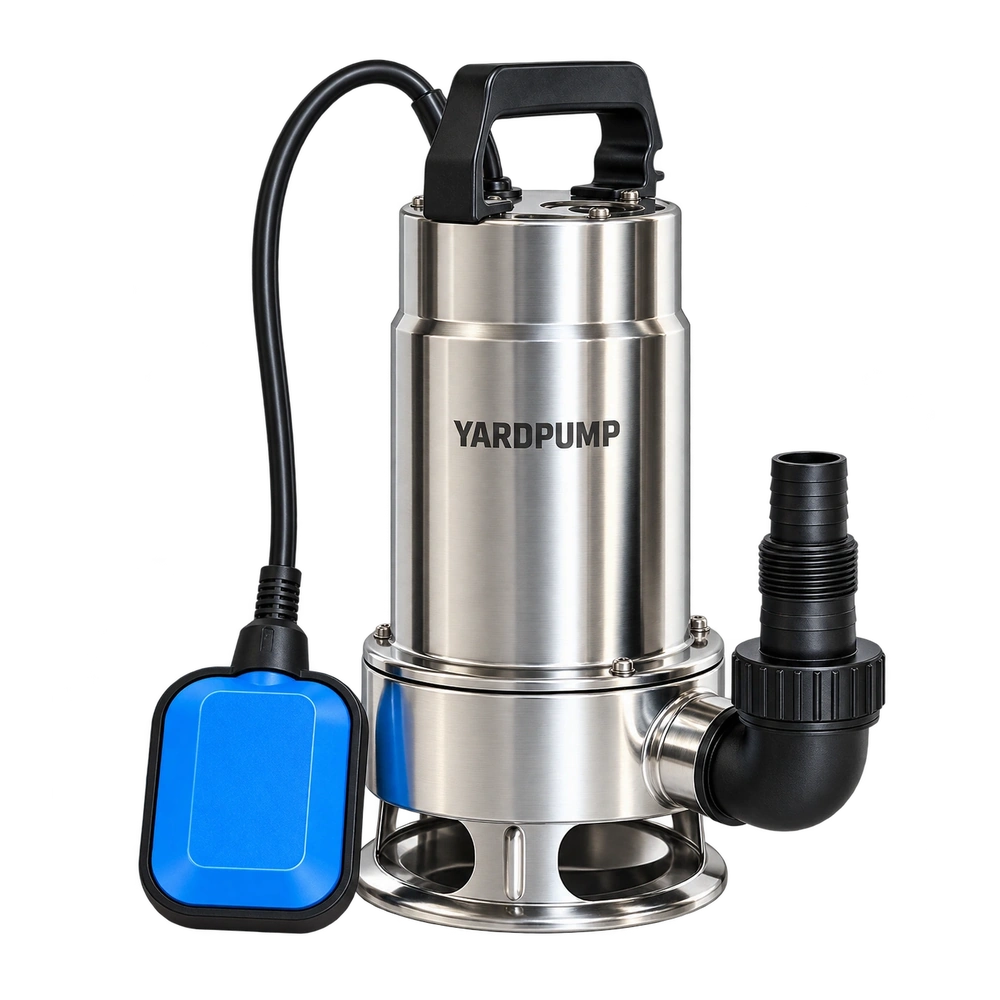
A moulded impeller gets a new finish on its back surface. Flow and head nearly match the previous tests, but the pump draws more electrical power. Has the motor lost efficiency, or is the finish at fault? Consider the power spent dragging liquid around the back of the impeller, then compare shaft torque and electrical input at the same speed and duty. Useful pumping work can remain nearly unchanged while the surfaces rotating near the casing take more power to turn.
Picture a disc spinning inside a wet case
Liquid next to the moving disc is dragged around with it. Liquid next to the stationary wall moves differently, so the fluid between the two is sheared. The outer edge travels faster than the inner part. Wetted surface area, diameter and angular speed can have a substantial effect on this loss. Roughness, clearance to the casing, recirculation and liquid viscosity can change it too. A roughness reading alone does not give the power penalty. Back vanes and leakage can change the flow behind the impeller. With an open design, establish which rotating surfaces and gaps actually exist before borrowing a model based on a solid shroud.
With the same flow, head and liquid density, useful hydraulic output is nearly the same. Shaft power can differ. Electrical input also includes the losses in the motor and its electrical parts. If the only evidence is a slightly higher wattmeter reading, consider motor temperature, supply, capacitor condition, bearing drag and seal drag alongside disc friction. Even a shaft-power change does not establish the cause on its own. Rubbing, a clearance error or a different internal leakage path can also increase shaft input.
Separate finish from clearance and other geometry
Retain the two impellers. Record back profile, diameter, any relevant balance or recirculation holes, face runout and the clearance to the case. On a qualified bench, use the same liquid, temperature, wet-end baseline and duty. Match speed for the design comparison and reverse the order across samples to reduce thermal drift. A test of a finish change is clearer if the vanes and axial clearances have stayed the same. Record torque, input, flow and head. Change surface and clearance separately if you need to estimate their contributions. Stop and isolate the equipment for inspection; do not expose a rotating shaft or impeller to get a closer look.
Suppose matched tests at 2,850 rpm repeatedly give an extra 0.10 newton metre of torque. In this illustration the angular speed is about 298 radians per second, so the shaft is taking roughly 30 more watts. Establish that the uncertainty and repeatability are good enough to resolve that difference. If torque is unchanged and only input rises, investigate the motor and measurement first. If the torque difference follows a controlled back-surface change, then check for marks, changed rear-chamber flow or load on the bearings before attributing it to fluid shear. These are example readings, not a pump specification.
Keep the two conclusions separate
On a clean-and-dirty-water pump, an installed test tells you whether the changed wet end produces an acceptable flow, input and temperature in service. A controlled shaft test can help decide which geometric change caused any difference. When only complete pump data are available, disc friction is a line of investigation, not a measured allocation of losses. Record the duties, clearances and liquid conditions that the approval actually covers.
Preserve the test order and temperature with the raw readings. If the rougher impeller was always tested after a long warm-up, the order itself is a plausible reason for a change in electrical input.
Frequently asked questions
Does polishing the back always save energy?
No. The effect depends on the geometry and flow behind the impeller. Compare speed, diameter and clearance before interpreting the surface alone.
Why can two pumps making the same hydraulic output need different torque?
Shaft power also covers internal losses such as fluid drag, recirculation and mechanical resistance. Useful delivery only accounts for part of the work.
Is seal friction the same as disc friction?
No. Disc friction here is the shear associated with a rotating wetted surface and adjacent liquid. Seal contacts and bearings need their own assessment.