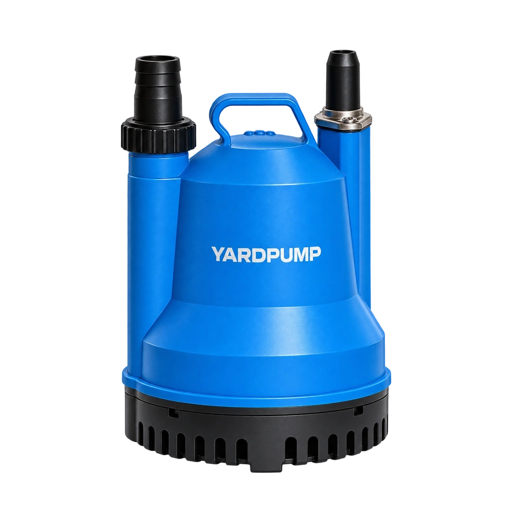
Consider this hypothetical loaded-motor comparison. “The motor has a long core and plenty of laminations. Why does it still struggle with the impeller fitted?” Core length is only one part of the design. A squirrel-cage induction motor also depends on effective current paths through rotor bars and end rings. Defects may affect torque, but supply, capacitors, windings and mechanical load can produce similar symptoms. One current reading cannot establish a broken rotor bar.
What the cage contributes
The stator field induces current in the rotor’s conductive circuit, and the interaction produces torque. Bars and end rings form part of that circuit. Manufacturing or service damage can disturb electrical continuity and create an uneven rotor-current distribution.
This does not mean that thicker bars are universally better, or that rotor weight alone ranks quality. Geometry, materials, electromagnetic design and manufacturing consistency work together. A longer core with an unsuitable winding or rotor arrangement still may not meet the required hydraulic task.
A useful investigation therefore starts with the complete operating requirement rather than assuming that a visibly substantial core must be electrically sound.
Neither high nor low current is a diagnosis
Impeller rubbing, bearing resistance, low voltage, a single-phase capacitor problem or a winding fault can cause difficult starting, heat or poor output. If the pump delivers less flow or head, its changed load may also reduce input readings. A lower reading is not direct proof of a rotor-cage defect.
Specialist electrical-signature methods may examine current-frequency components associated with slip. However, supply conditions, load variation and other mechanical effects also influence signals. A spectrum without stable operating conditions, speed and supply information is not a complete diagnosis.
Use qualified personnel with relevant experience. A technique that works well on one motor size or construction may not produce equally clear evidence on every compact portable pump.
Establish a comparable load first
| Investigation level | Required information |
|---|---|
| Supply | Pump-terminal voltage, frequency and starting changes |
| Hydraulic task | Actual flow, head, liquid and operating point |
| Motor behaviour | Acceleration time, speed, settled current and temperature |
| Single-phase arrangement | Capacitor, auxiliary circuit and approved connections |
| Mechanical condition | Bearings, rubbing, clearances and foreign material |
This first stage helps exclude obvious external or system causes. When comparing samples, align the task and conditions as far as practicable. A lightly loaded motor’s current cannot be ranked directly against another unit doing more hydraulic work and then attributed solely to rotor quality.
Retain the baseline from an approved sample. It makes later changes in acceleration, speed and output easier to investigate without inventing an arbitrary current threshold.
Build evidence progressively
After basic checks, specialists may select electrical-signature, vibration or other appropriate diagnostic methods for the motor. Interpret them together with speed, load and temperature records. Several consistent observations are more useful than an isolated anomalous peak.
If dismantling or a dedicated rotor examination is necessary, isolate the supply and use competent personnel following an approved procedure. A dark mark, visible pore or unusual spectral component needs interpretation in its location and operating context. It should not automatically become “broken bar confirmed.”
Preserve the original failure record and components before grinding, striking or attempting an improvised repair. Destructive work can remove information needed to establish whether the defect originated in manufacture, assembly or later service.
Control the risk through OEM approval and production
Sample approval should demonstrate motor-load matching and retain starting, speed, hydraulic-performance and temperature baselines. The supplier should control rotor material, casting or connection processes and relevant changes. Purchasers can request manufacturing and quality evidence rather than treating lamination count as the complete quality requirement.
If production shows a change in starting or output, quarantine affected units and compare batches, rotor and stator configurations, materials and process changes. If a cage defect is confirmed, investigate its origin, distribution and suitable screening. One returned pump cannot establish a batch-wide or industry-wide failure percentage.
Write conclusions to match the evidence
A confirmed finding should identify the defect, method and connection to the symptom. Where evidence remains incomplete, record the need for further diagnosis instead of closing the complaint with an unsupported certainty.
After repair or replacement, repeat the required complete-pump performance and safety checks. Successful unloaded rotation does not establish that the motor can deliver the intended task safely.
Frequently asked questions
Can a high lamination count rule out a rotor defect?
No. Stack length and cage-circuit integrity are different characteristics. Lamination count does not establish acceptable bars, end rings or manufacturing quality.
Can an ordinary multimeter identify every broken bar?
No. Cage geometry and low-resistance paths require appropriate methods. One ordinary reading is generally insufficient for a complete conclusion.
Should poor torque first be treated with a larger capacitor?
No. Departing from the approved capacitor arrangement can introduce heat or other risks. Check supply, mechanical condition and starting circuitry before making a motor-specific diagnosis.