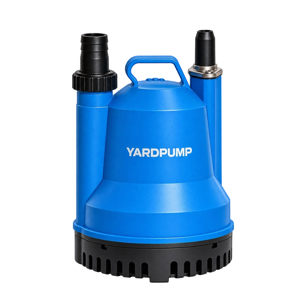
Two submersible motors have stator and rotor cores of equal length. Does that establish the same effective assembly? Position still matters. Length describes how long a component is; axial location describes where it sits. Check the core relationship through the housing datums, shaft shoulders and bearing locations rather than comparing stack length alone.
Draw the intended relationship first
A photograph of two stacks is not an assembly specification. On a section drawing, identify both ends of each core, the shaft shoulder, bearing locations and housing reference surfaces. Some designs intentionally use unequal lengths or particular end relationships. Perfectly flush ends are not a universal acceptance rule.
The question is whether the completed motor matches its approved design. Stator insertion depth, rotor position on the shaft, end-cover registers and locating components can all affect the relationship. Individually conforming components may still be assembled incorrectly if a datum is misunderstood or a part is not seated.
Distinguish a drawing dimension from an inspection instruction. The latter must explain which surface establishes position and which assembled condition the measurement represents.
Equal lengths can give different overlap
Consider a simplified, hypothetical geometry. Both core lengths are 40 mm. If their axial positions differ by 3 mm, their geometric overlap is 37 mm. This illustrates why location matters. It does not demonstrate a 7.5% reduction in shaft power, nor support a proportional efficiency calculation.
Actual electromagnetic behaviour depends on end effects, windings, air gap and the complete design. An axial discrepancy may warrant investigation of magnetic forces, noise, temperature and mechanical margins. It does not explain every possible symptom, and successful starting does not cancel a dimensional nonconformity.
| Check | Shared reference needed | Common omission |
|---|---|---|
| Stator insertion | Housing register and core end | Different insertion-depth datums |
| Rotor position | Shaft shoulder and rotor end | A component not fully seated |
| End cover and bearings | Locating shoulders and specified spacers | Missing or mixed-revision parts |
| Completed assembly | One defined assembled condition | Nominal part dimensions replacing measurement |
Exclude measurement differences
A chamfer, insulating part or projecting winding is not necessarily the effective core end. Identify the measurement surface before comparing readings. Photographs need an established direction and scale; calipers placed on different features can produce different apparent lengths without any manufacturing change.
Define the shaft position during an assembled check. If axial freedom exists, measurements taken with the shaft at opposite ends of its travel may not be comparable. A fixture must not force components into a position they do not occupy in the specified assembled state.
Opening a motor requires electrical isolation, management of stored capacitor energy and qualified personnel following the manufacturer's procedure. Dimensional investigation is not a reason to bypass protection or operate an exposed assembly.
Avoid an informal spacer repair
Adding a washer may move the rotor, but can also change bearing preload, seal working length, impeller position and mechanical clearances. Correcting one dimension while disturbing another function is not a controlled solution.
Trace the discrepancy through drawing revision, assembly tooling, pressing position and locating components. Establish which link departed from the intended dimension chain. If a design change is necessary, give the revised configuration its own identity and verify the affected functions together.
Compare actual performance, real input power, temperature behaviour and relevant mechanical condition under equivalent supply and hydraulic conditions. A satisfactory no-load current does not establish unchanged loaded pump performance.
Ask for useful purchasing evidence
A buyer does not necessarily need every proprietary drawing. A technical dispute does require enough information to verify the critical references, tolerances and sample identity. Record lamination count, stack length and axial location as separate facts. The phrase “the cores are the same” can otherwise conceal different meanings on each side.
These are general assembly principles. They do not establish an approved dimension or permissible offset for any particular YARDPUMP model.
Frequently asked questions
Must the stator and rotor ends be perfectly flush?
Not universally. Follow the specific electromagnetic and mechanical design rather than a visual rule.
Does a 3 mm offset mean a proportional loss of power?
No. Geometric overlap cannot be converted directly into shaft output or efficiency.
Can an extra washer correct the position?
Not without engineering verification. Bearing, seal and impeller locations may change at the same time.