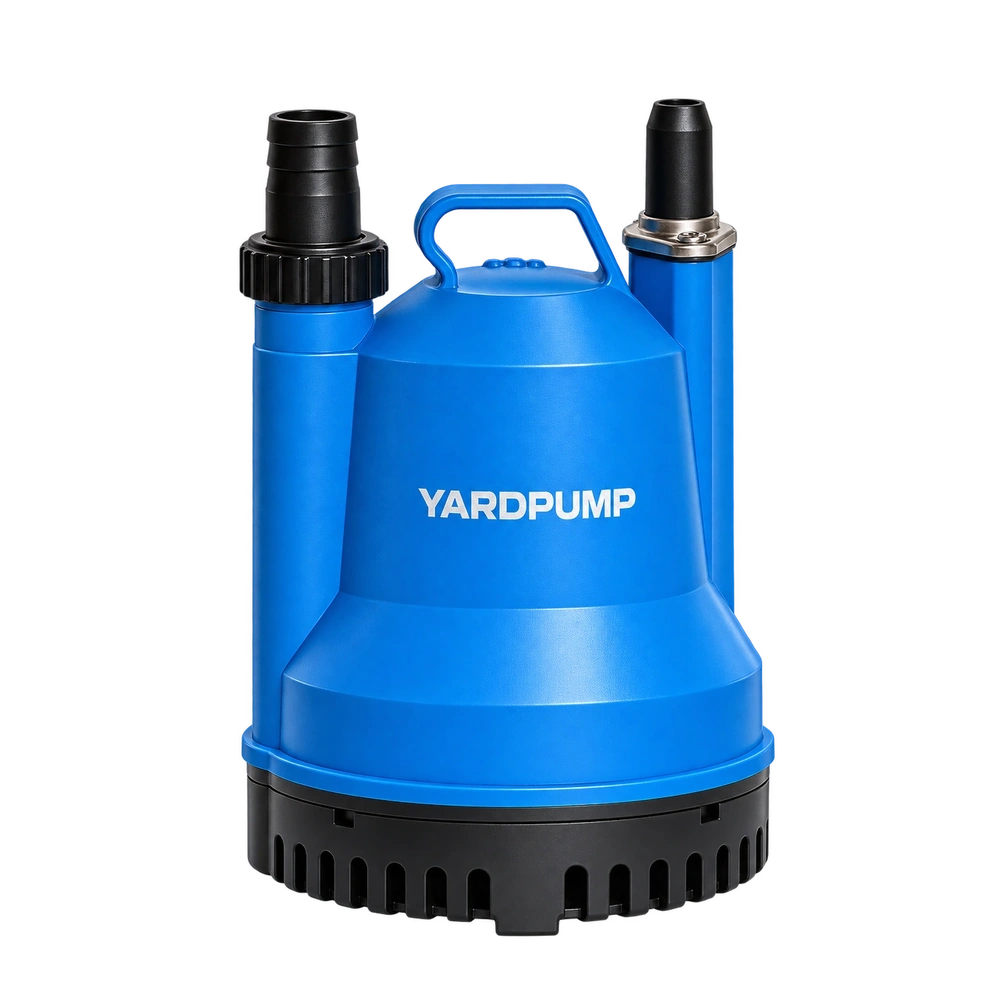
Closing a discharge valve can reduce the flow while raising the head developed by the pump. To see what happens to power, measure real electrical input and calculate water power at the same operating point. A motor wattage label and the valve position cannot tell you how much useful work the system is doing.
Calculate water power at the actual point
The valve adds system resistance. At the new intersection with the pump curve, the pump typically develops more head at lower flow. Hydraulic output is proportional to flow times head, while motor input also includes hydraulic and mechanical losses.
For water close to ordinary temperature, multiply density by gravity, flow in cubic metres per second and total pump head in metres. The answer is hydraulic power in watts. Use total head across the pump, determined from the test setup, with the same reference points each time. A gauge installed after the regulating valve will usually omit part of the head the pump develops.
Here are two illustrative test points for clean water. At 60 L/min and 6 m, hydraulic power is about 59 W. At 40 L/min and 7.5 m, it is about 49 W. The rise in head does not make up for the reduction in flow. If a real-power meter reads 180 W and 165 W respectively, the ratio of water power to electrical input changes from about 33 percent to 30 percent. The values are for calculation only.
Keep input power, shaft power and water power distinct
At several permitted valve positions, measure flow, total head, voltage, real input power, current and water temperature. Compare only after readings stabilise and stay within the released operating range.
Electrical input supplies motor losses and power to the shaft. The shaft drives the wet end, which also has losses. Water power and real electrical input give an overall ratio. To infer shaft output you need separate motor efficiency evidence at that load or a suitable shaft measurement. The electrical power falling by 15 W in the example does not say where every watt went.
The valve consumes some head in the form of pressure loss. Compare the head developed by the pump with the lift and pressure actually useful at the destination. This matters on a system that is throttled heavily day after day. Use a duty calculation to decide whether a different pump or eligible control arrangement would leave less loss in the valve.
Work inside the permitted flow range
Use the valve for controlled duty adjustment only where the model and system permit it. Select a better-matched pump or control method if permanent severe throttling is required.
Do not run at shutoff or outside minimum-flow and cooling limits unless the exact model documentation permits the condition.
At very low flow, some designs can heat the liquid or develop adverse internal flow even with a lower measured input. For acceptance work, record flow, head and input at the same time and finish testing at the model's boundary. Do not use a reduced meter reading alone to justify a restricted installation.
Frequently asked questions
Does an increase in gauge pressure mean the pump gives the water more power?
Read pressure location, total head and flow together. Hydraulic power is proportional to their total-head and flow product.
Can I calculate shaft power from flow, head and wall watts?
Those readings give water power and the overall ratio. Shaft power needs separate evidence about the motor at the measured duty.
Is throttling worthwhile if power goes down?
Compare the work delivered, power drawn and the allowed flow range at the duty you need. For repeated service, consider the total time required to move the specified water.