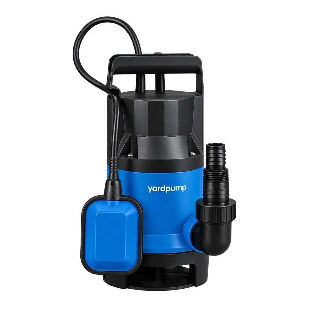
Consider the following hypothetical speed-control request. “The single-phase capacitor pump delivers too much water. Can we slow it with a lighting dimmer or an ordinary variable-frequency drive?” Not without confirming compatibility. Identify the motor construction, then check drive output, starting arrangement, cooling and hydraulic limits. A drive with single-phase input may provide three-phase output; that label does not make it suitable for a single-phase capacitor motor.
Identify the motor behind the plug
Single-phase induction motors can use different auxiliary windings, capacitors and starting devices. A permanent-split-capacitor motor is not the same control proposition as an arrangement with a starting capacitor or starting switch. Similar pump housings and identical supply plugs do not establish identical motor construction.
Dedicated drives do exist for specified single-phase motor types. It is therefore also inaccurate to say that no single-phase motor can ever be speed controlled. However, those drives have defined supported topologies and operating restrictions. Their existence does not establish compatibility with every capacitor pump or generic controller.
Obtain the actual motor identification and approved control method. If the relevant information is unavailable, do not use trial connection as the method of identification.
Distinguish three different types of equipment
| Equipment | Information to establish | Common mistaken assumption |
|---|---|---|
| Lighting dimmer or basic voltage regulator | Explicit approval for the particular motor load | Lower voltage produces a stable proportional reduction in speed |
| General-purpose frequency drive | Input phases, output phases and supported motor types | Single-phase input means single-phase motor output |
| Dedicated single-phase motor drive | Supported topology, wiring and rating range | Any device marked single-phase supports every capacitor arrangement |
Unsuitable voltage control can reduce available torque, increase slip, cause overheating or prevent starting. Sound and visible water movement are not adequate compatibility tests.
The pump also changes when speed changes
Speed affects the pump curve, while the system determines the actual operating point. In a system with substantial static lift, reducing speed may eventually leave insufficient head to move useful water. The motor can still rotate while the pumping task is no longer achieved. A speed percentage is not automatically the same percentage of installed flow.
Cooling, bearings and seal operation also need assessment. Where the pump relies on surrounding water or specified circulation for cooling, lower hydraulic output does not automatically mean lower winding temperature. Any additional electrical effects from the drive, together with the minimum permitted continuous speed, require evaluation by the motor and complete-pump manufacturers.
Do not apply simplified speed relationships beyond their assumptions or use them as a substitute for a confirmed operating range.
Request evidence for the actual OEM combination
Obtain the complete motor type, ratings, winding and capacitor arrangement and permitted control method. Ask the drive supplier to confirm output type, supported range, protection and wiring. Both parties’ documents should identify the same configuration rather than merely attaching unrelated general manuals.
Validation should cover starting, the lowest and highest approved speeds, the intended hydraulic task, temperature rise, protective behaviour and restart conditions. Existing floats, pressure switches or electronic controls also need review. Their positions and switching logic must be compatible with the drive’s instructions.
In particular, do not assume that repeatedly switching an existing control in the drive’s output circuit is permitted. The approved arrangement should define how commands and isolation are achieved.
Start with the customer’s actual problem
A distributor should establish whether the objective is lower flow, lower pressure, fewer starts or energy reduction. These are different problems. Some systems may use approved valve adjustment or a more appropriate pump selection, but minimum flow, pressure and thermal limits still apply. “Close the valve” is not universal advice.
Where speed control is needed, use a confirmed pump-and-controller combination. Qualified personnel should perform electrical installation and testing with proper isolation. Do not instruct users to alter capacitors, bypass protection or improvise winding connections. An unvalidated modification cannot simply inherit the original complete-pump conclusions.
Frequently asked questions
Will buying a larger drive solve compatibility?
No. Capacity margin does not change output phases, motor topology or the control method. Establish compatibility first, then size the approved combination.
If the motor rotates, has the speed-control arrangement passed?
No. Starting reliability, torque, temperature rise, protection and useful hydraulic output still need validation. Brief rotation or lightly loaded pumping is insufficient.
Can a DC or electronically commutated pump use the same selection method?
No. Its power and control arrangement is different. Follow the requirements for that specific pump and controller rather than transferring capacitor-motor assumptions.