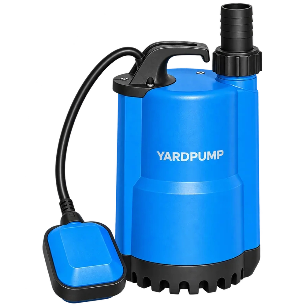
An illustrative proposal for insufficient head is the following. “Our submersible pump cannot reach the required head. Will adding another in series double it?” Pumps in series add head at the same flow, but the installed flow still depends on the system curve. More critically, the downstream pump and connecting equipment may experience additional inlet pressure. Maximum immersion depth is not a substitute for an approved series-operation pressure rating. Do not improvise this arrangement without manufacturer confirmation.
Add head at a common flow
In series operation, both pumps add energy to the same stream. A theoretical combined curve adds their heads at each common flow, then intersects that curve with the system curve to establish the operating point. Combining one pump’s maximum flow with another’s maximum head has no useful hydraulic meaning.
For illustration only, suppose each pump produces 10 m head at the same flow. Ignoring connecting losses, their combined head at that flow is approximately 20 m. Once connected to a real system, they may not operate at that original flow, and the connection losses remain. The example does not establish a guaranteed doubling of installed flow or final head.
Use complete curves for the actual configuration and supply conditions. Check the resulting point against both pumps’ approved operating ranges.
The downstream assembly may reach a pressure limit first
The second pump receives pressure created upstream before adding its own energy. Its outlet and relevant casing regions may therefore experience higher pressure. Stopped flow, closed valves, control faults and transient conditions also require assessment; a normal running gauge value is not the entire pressure case.
Confirm maximum inlet pressure, casing and seal-chamber limits, and the ratings of connections and hoses separately. Immersion depth concerns an external water-pressure condition. It does not automatically prove suitability for an equivalent internal inlet pressure or for changed pressure differences across shaft seals and cable entries.
A pump that is acceptable when discharging from an open sump may therefore be unsuitable as a pressurised downstream stage, even if its hydraulic curve appears attractive.
Check four groups of limits
| Boundary | Required confirmation |
|---|---|
| Hydraulic operation | Individual curves, combined operating point and minimum permitted flow |
| Pressure | Inlet, casing, seal and connecting-component limits |
| Electrical and control | Starting sequence, interlocks, protection and power-loss state |
| Installation | Connections, supports, maintenance access and pressure isolation |
If the pumps differ substantially, one may create unsuitable conditions for the other. A stopped pump may restrict flow or be driven by passing liquid. Whether either pump can run alone, and whether liquid may pass through a stopped stage, depends on the construction and approved system logic.
Two plugs do not constitute a control design
Define the response to dry running, obstruction, one pump’s protective trip and loss of supply. If the upstream pump stops while the downstream unit continues, the latter’s inlet conditions change. If the downstream pump stops while the upstream unit continues, pressure and loading on stopped components may change.
The actual consequences depend on the pumps, pipework and valves. Do not prescribe one universal starting sequence from a simplified diagram. Competent designers should determine interlocks and pressure protection, with qualified personnel handling electrical installation and acceptance.
Do not bypass original protection or improvise pressure tests on unconfirmed plastic connections. Commission under an approved procedure with suitable isolation and protection rather than asking users to stand beside pressurised joints looking for leaks.
Compare the complete alternative
A series arrangement may add controls, valves, supports, maintenance and energy costs as well as another pump. A suitable single pump or an approved booster system may be easier to manage, but compare each option against the actual flow, liquid and duty.
Distributors should obtain static lift, required flow, pipe length and diameter, supply and control requirements before proposing changes. First exclude an obstructed line, collapsed hose or unsuitable operating point. Adding a stage should not hide an installation fault that remains unresolved.
Frequently asked questions
Does using two identical pumps guarantee adequate pressure capability?
No. Identical models simplify curve comparison but do not establish permissible inlet pressure or casing and seal limits.
Is series operation necessarily more energy-efficient?
No. Compare total input power while delivering the same task, including relevant control and pipe losses. Individual nameplate power is insufficient.
Does an IPX8 marking prove suitability for high-pressure series operation?
No. Enclosure ingress protection under specified immersion conditions is not a universal internal-pressure rating for the flow path and all components. The actual design still needs confirmation.