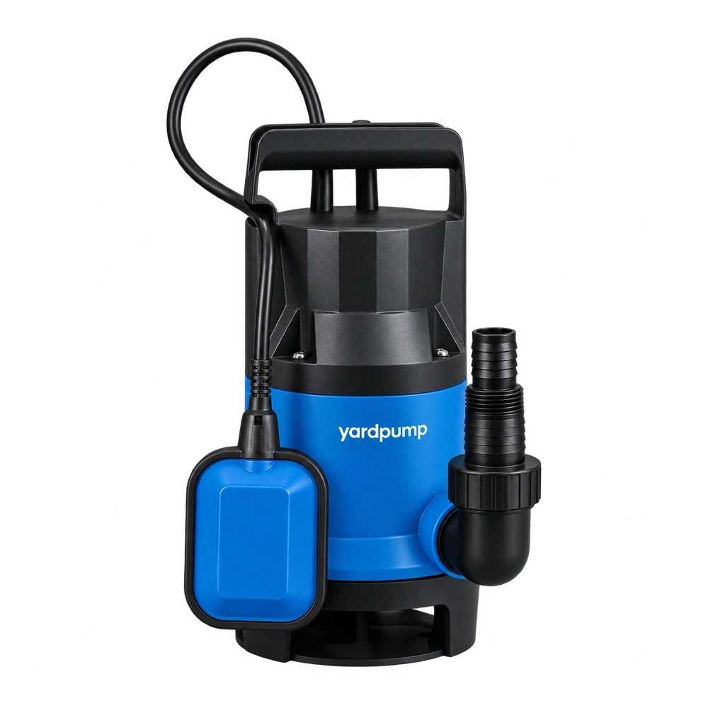
Water enters a shallow sump from one side. Just after the pump stops, a wave passes the level switch and the motor starts again. The first thing to establish is whether the controller received a new start signal. A chattering command caused by moving water calls for a different remedy from a damaged switch, unstable control power or a pump that stops while still being commanded to run.
Put the level and the command on one timeline
A pump controller normally has separate start and stop levels or another approved method of avoiding rapid cycling. The difference is called hysteresis or differential. An inlet jet can raise the water locally around the sensor without filling the whole sump. A reflected wave can cross a threshold twice, and a quick volume of backflow can raise the entire level. A tethered float can also change angle when it hits a pipe or is pulled by a turbulent stream. These are different mechanisms that can produce a similar sound.
Record a level mark away from the jet, the sensor location, the pump status and the interval between events. A time-stamped video taken from a safe position can help synchronize visible motion and the pump’s operating indication. A qualified technician may separately record controller input and output with approved equipment. If the input changes first, investigate motion at the sensor or its circuit. If input remains stable while controller output drops, examine the controller or control supply. If both remain steady but the pump stops, isolate it and refer the power and protection circuit to qualified service. Do not bridge a switch or bypass a protection function to force an answer.
Test the installation, then choose an approved remedy
Compare a quiet, controlled fill with the normal inflow, using the same installation and safe operating limits. Note whether the pump stops well before it draws air and whether the starting level leaves enough room below overflow. A difference between quiet and turbulent fills directs attention toward sensor placement, inlet direction or an approved calming arrangement. A change to switch differential also changes stored volume and can affect emergency capacity, so it must be checked against sump geometry and pump limits. Leave room for the float to move through its full travel, including at the extremes.
In an illustrative test, an inlet surge moves the local surface about 25 mm, while a small pump chamber is set to switch levels only 20 mm apart. That is enough reason to log the crossings rather than assume a failed contact. After a manufacturer-approved sensor relocation, compare the same incoming surge again. If the true bulk level is climbing on shutdown, examine return flow and drainage instead; shielding the sensor from genuine rise can hide a real alarm condition.
Check the change at both normal and high inflow
Keep the original switch settings and changes in the service record. A calm water test alone does not validate a correction to slosh. Confirm multiple starts and stops under a representative inflow, watch the final level, and check any approved high-level alarm independently. When a design permits a short debounce, that setting is a way to filter brief signals; it also creates a delay. Verify its consequence at high inflow and retain a safe reaction path. A continuous leak, frequent unexplained tripping or an electrical fault calls for isolation and service rather than longer filtering.
Frequently asked questions
Does a new float eliminate turbulence-related cycling?
Only if its movement and switch behavior suit the installation. A replacement mounted in the same jet may see the same fluctuating level.
Should I always make the start and stop levels farther apart?
No. Confirm usable pit depth, reserve above the start level, the pump’s minimum operating level and the permitted control settings.
Can I diagnose the issue from a clicking relay alone?
No. Synchronize the sound with level, switch input, controller output and pump state; different faults can make similar clicks.