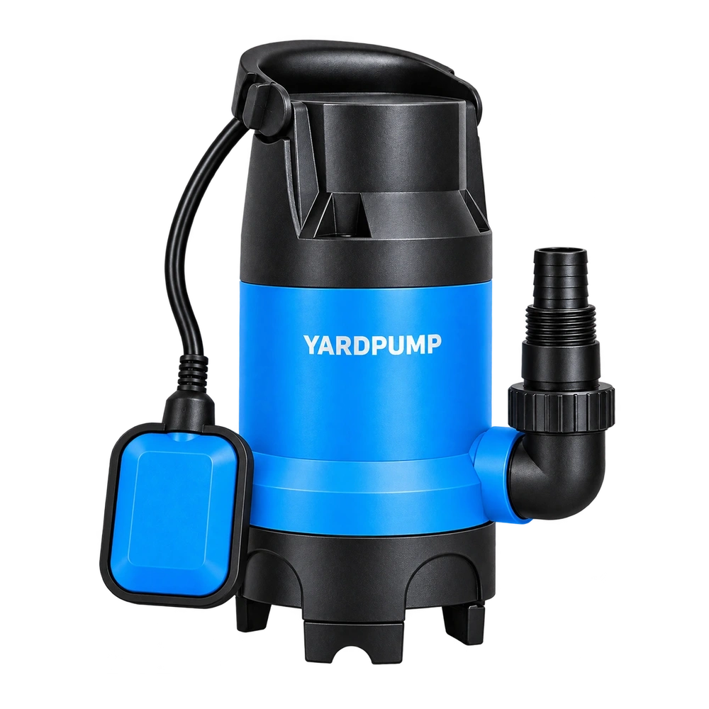
Two portable pumps sit in separate sumps and join at a tee before one long hose. Only one is running. The other sump starts rising, and water appears near the intake of the unplugged pump. If the rise begins while the active pump is running, think about a path through the tee and back through the idle branch. The outlet may still be delivering water at the same time. Checking the idle side can prevent a mistaken diagnosis of poor pump capacity or a blocked main hose.
What the tee connects
The operating pump raises pressure at the junction to move water to the final outlet. From that junction, water can follow more than one route. If the idle branch has no effective check valve and pressure at the tee is high enough relative to water in its sump, water can pass backward along that branch. A stationary centrifugal impeller does not generally close the hydraulic passage. The pipe can therefore carry some of the active pump’s delivery to the final outlet and some through the idle pump.
This symptom is different from the water retained in a riser falling back after both pumps stop. Timing helps: a sustained rise or reverse plume at the idle sump while its neighbour runs suggests crossflow. A short rise only after shutdown suggests drain-back instead. Water from the final hose end running over the ground into the sump is another possibility. Trace the full discharge destination before attributing an increase to the tee.
Locate the split without opening a live line
Start by recording the water depth in both sumps, which pump is powered, the tee location, elevation of the final outlet, and any check valves. Photograph accessible valve arrows and connection labels, without moving fittings while the system is running. Observe from a dry, safe location. Keep people clear of both pits and of hoses that might move. Where information cannot be obtained safely, turn the system over to an installer.
Compare the idle sump level with the active pump off and then, if the ordinary operation is safe, while it is delivering through the existing line. Note independent inflows and whether the visible water begins at the pump base. In a controlled clean-water setup, if the idle basin has a constant area of 0.30 m² and rises 40 mm in two minutes with no other inflow, that is about 12 litres, or an average of 6 L/min into that basin. This is an illustration, not a universal loss. A sump with variable area or background inflow needs an appropriate volume estimate and baseline correction.
A stronger comparison, when the equipment and drainage plan allow it, is temporary independent discharge for the active pump to a safe, equivalent endpoint. The inactive pump then has no hydraulic connection to it. Arrange and remove hoses only with both pumps isolated and trapped pressure relieved; fixed installations should be adapted by qualified personnel. If the idle sump no longer rises and the final outlet recovers flow, inspect the branch arrangement for a reverse path. Avoid blocking a working line or relying on wiring changes for this comparison.
Decide between a separate route and designed parallel discharge
Separate approved discharge routes can be practical for temporary work where the outlets have suitable destinations. For a retained shared line, have the installer check each branch for the manufacturer’s approved check valve, position, direction, operating pressure and solids capability. A valve can fail to seat because of debris or because its design and orientation do not suit the water and flow. It also adds resistance, so prove that one pump working alone and both pumps working together can meet their respective duties.
Do not rely on a single check valve after the tee to stop transfer between branches upstream of it. Restore automatic control, confirm the idle branch and watch an ordinary single-pump to two-pump transition within the agreed operating limits. Record the results with the final layout so the next crew can distinguish crossflow from a later blockage.
Frequently asked questions
Does seeing flow at the hose end rule out crossflow?
No. Some water can reach the endpoint while the rest goes back into the idle branch.
Why might the check valve leak only during some cycles?
Debris, marginal seating, or different pressure at the junction can change the reverse path. Check the actual valve and procedure rather than assuming a universal cause.
Will a larger shared hose solve it?
A larger hose may reduce junction pressure at a given flow. It is not a substitute for approved protection against reverse flow between connected branches.