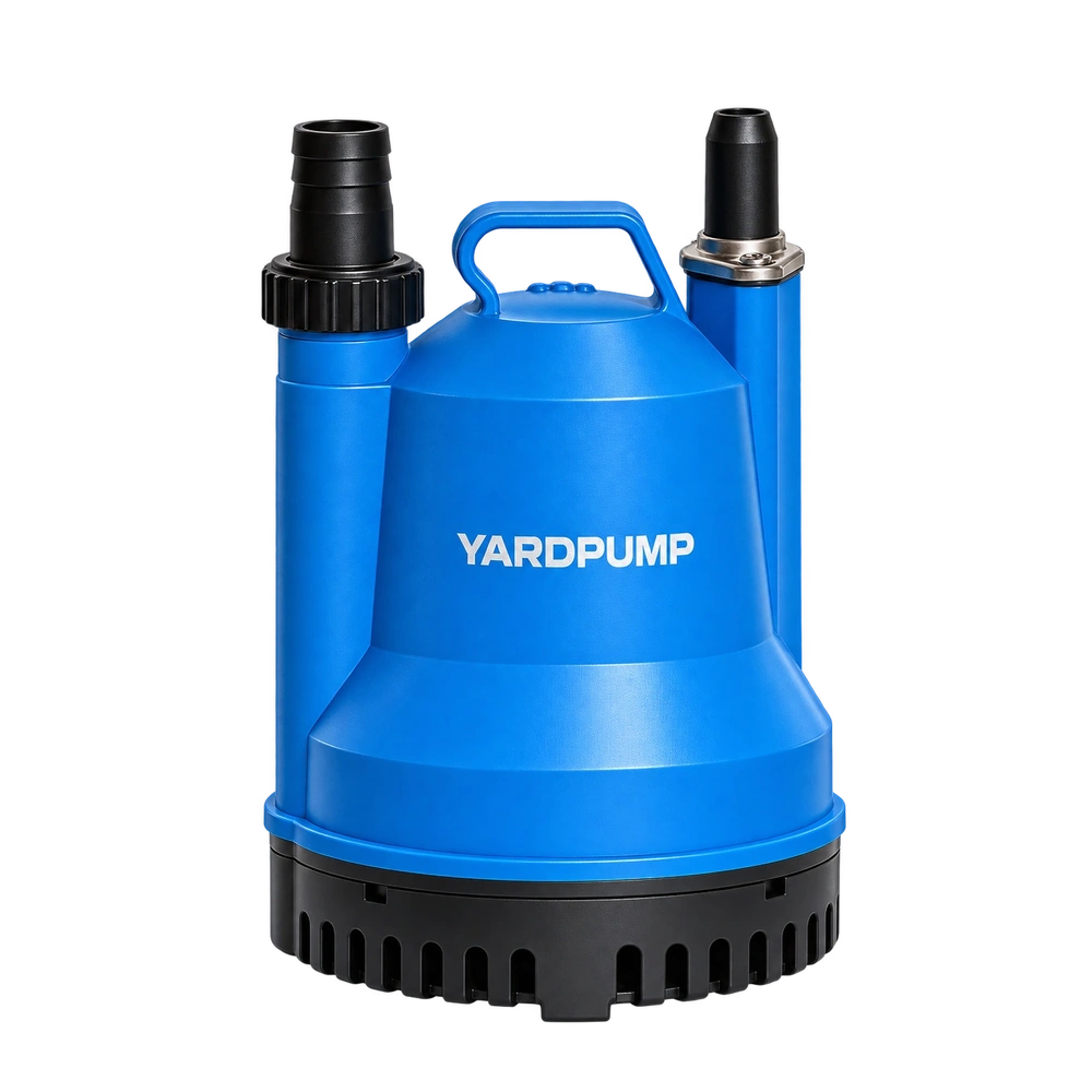
Imagine a sump level has dropped below the usual stop line, but the pump keeps delivering and then begins to draw air. One person suspects welded contacts; another says the controller has a delay. Stop and isolate the pump by the approved safe method. Do not leave it running at a low level to see what happens. The investigation has three parts: whether the actual stop condition was reached, whether the controller still requested operation, and whether the motor output released when commanded.
Confirm when the pump should have stopped
Some floats have different start and stop levels, and a replacement may not use the previous visual reference. The system may include a minimum run time, an off delay, another float or a manual mode. Record the actual water level, float position, control indication and timing settings. If water has dropped below the permitted intake or cooling condition, make the equipment safe before investigating. Compare the record with the approved instructions and configuration. The sound of a motor is not an electrical output measurement.
Observations from a safe dry position can show an alarm, display state or discharge. Opening an enclosure, measuring a circuit or inspecting contacts is for qualified personnel after isolation, verification of the safe condition and management of stored energy. Do not touch a live float, pull the pump out of water or bridge a control to force a response. Identify any additional supply or standby equipment as part of the isolation plan.
Put level, command and output on one timeline
If the controller still indicates a run request at the expected stop position, investigate the sensor movement, remaining signal, manual state and approved delays. If the request has ended but a qualified controlled test shows that the output did not release, investigate the switching stage. Welded contacts are one possibility; another supply path can produce a similar symptom. A dark indicator does not prove the motor terminals are safe, and contact appearance alone does not establish the failure. Use the approved test environment and method.
For illustration, suppose a controller has an agreed ten-second off delay. The request remains for about ten seconds after the actual stop condition, and the request and output then both end. That pattern is consistent with the setting. In another hypothetical test, the command ends but the output remains active under the permitted test conditions. That is stronger evidence to investigate the switching stage. Ten seconds is not a recommended delay. Even an intentional delay requires review if the installation reaches a prohibited low level before the pump stops.
Verify the actual stopping window after repair
After an approved repair, check start and stop levels, minimum cooling conditions, command state and actual output. Repeat the relevant checks for delays, alarm or standby functions if they belong to the original system. If a relay or contactor failed, verify that the load and starting conditions match the approved component. Do not substitute one because the body looks similar. If the float was blocked by a wall or hose, restore the approved geometry and verify the switching level rather than holding it temporarily. The service record should identify which stage failed to follow the preceding state. That helps prevent the same fault recurring on a replacement pump.
Record the supply mode and how quickly the level fell. If the report concerns heavy inflow or standby power, retain that context. A single normal dry simulation does not disprove the field event.
Frequently asked questions
Does running after the level drops prove the contacts welded?
No. A run request, manual mode or delay may still be present. Make the equipment safe and have the stages checked.
Is a dark indicator enough to start dismantling?
No. Verify isolation of all sources under the approved procedure.
Will a larger contactor fix it?
Identify the failed stage and actual load first. Use the approved component and confirm the complete control function.