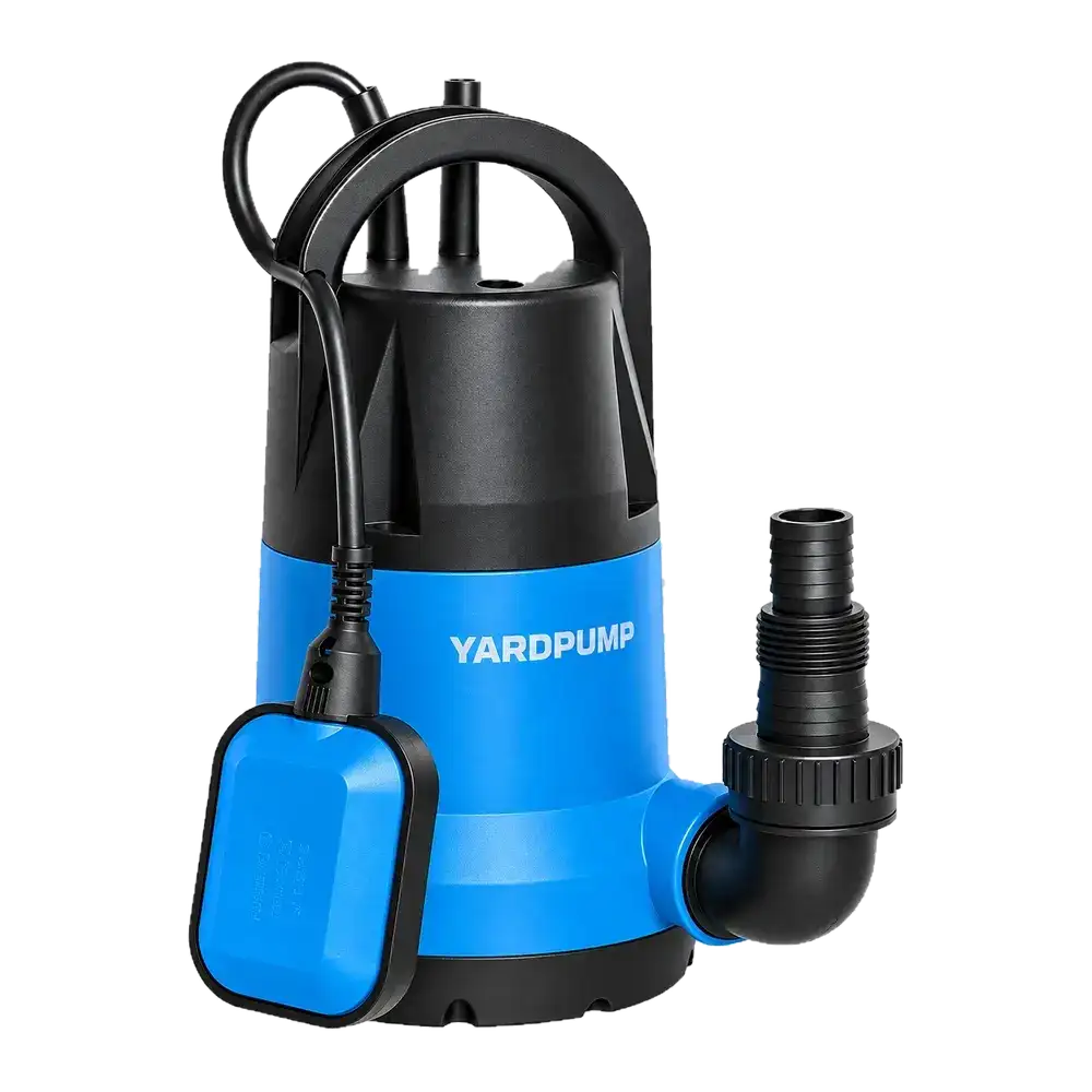
Consider two pits, each with its own submersible pump, whose discharge branches share a header. Pump A starts and the level in pit B climbs although pump B is off. Trace whether some of A’s discharge is finding a way down B’s branch. A check valve beyond the junction does not necessarily isolate the two branches. Visible discharge at the common outlet does not rule out simultaneous flow into the other pit.
Find the possible branch path
During A’s run, pressure at the junction can send water towards B if there is an open path and enough pressure difference. It can return through B’s discharge branch and an idle pump or another connected path. Examples include a missing branch check valve, incorrect orientation, debris, a damaged seat or a bypass added during an earlier modification. Trace the actual piping before naming the check valve as the failed component.
Compare this with two other situations. After a normal stop, water held in a riser can return to its own pit. That level change follows shutdown. With crossflow, the other pit rises while the first pump is running. Water discharged onto unsuitable ground can also reach a collection pit by an external drain or through the ground, often after a delay. Rain can increase inflow to both pits. Find out whether the extra water is returning through the discharge side or arriving at the ordinary inlet.
Record both levels against pump states
From a safe dry position, record rainfall or normal inflow, A’s starts and stops, B’s state and both water levels. Use only approved viewpoints to look for a change in B’s normal inflow. Do not open or enter an inaccessible pit to identify a jet. The responsible staff can arrange A-only and B-only operation within normal limits while maintaining flood protection and leaving the discharge route as designed. A reverse leakage check or temporary instrument should be arranged by qualified personnel, with power and automatic starting isolated, retained pressure controlled and sanitation procedures followed. Do not shut a running pump’s outlet as an improvised test or leave the other pit without drainage protection.
As an illustration, suppose a calibrated level band in B gains 30 L in one minute while its normal inflow is approximately 5 L/min and B delivers no water. About 25 L/min of additional water is a clue, not a calibrated measurement of valve leakage. Look for where the water entered, timing against A and changes in background inflow. A rise synchronized with A and no change at the ordinary inlet makes pipe crossflow more plausible. A delayed rise during changing rainfall still warrants an investigation outside the header.
Confirm each branch works on its own after repair
Mark each check valve, its direction, any service isolation and any bypass on a piping sketch. Have the responsible people confirm that each check device suits the liquid, opens and reseats, and can hold the relevant reverse pressure when required. After correction, observe A-only, B-only and the simultaneous mode if the system permits it, over comparable water levels. Confirm that a running pump is no longer feeding the other pit and that both deliver and stop correctly. Flow at the common outlet alone is not enough.
This check is for separate pits connected by branches. Sewage, hazardous mixtures and external pressure mains need the applicable design and maintenance procedures. A simple clean-water observation is not a substitute for them.
Frequently asked questions
Does a check valve after the junction protect the other pit?
It can block backflow from downstream of that valve. It does not necessarily stop flow from one branch into the other before it.
How can water enter B when pump B is off?
Some paths can pass water in reverse while a pump is stationary. Have staff trace the actual pipework; the electrical state alone cannot rule it out.
Is a run of pump A enough to verify the repair?
Verify each branch in turn where permitted, then the overlapping operating mode if used. Check discharge and automatic control as well as the levels.